I. Concept of precision bore honing
To create a machine, device, or production line, several steps must be followed. First comes the design idea ⇒ Assembly drawing design (2D or 3D) ⇒ Creating detailed drawings (also called precision bore honing drawings) ⇒ Machining ⇒ Assembly ⇒ Inspection ⇒ Packaging ⇒ Deployment.
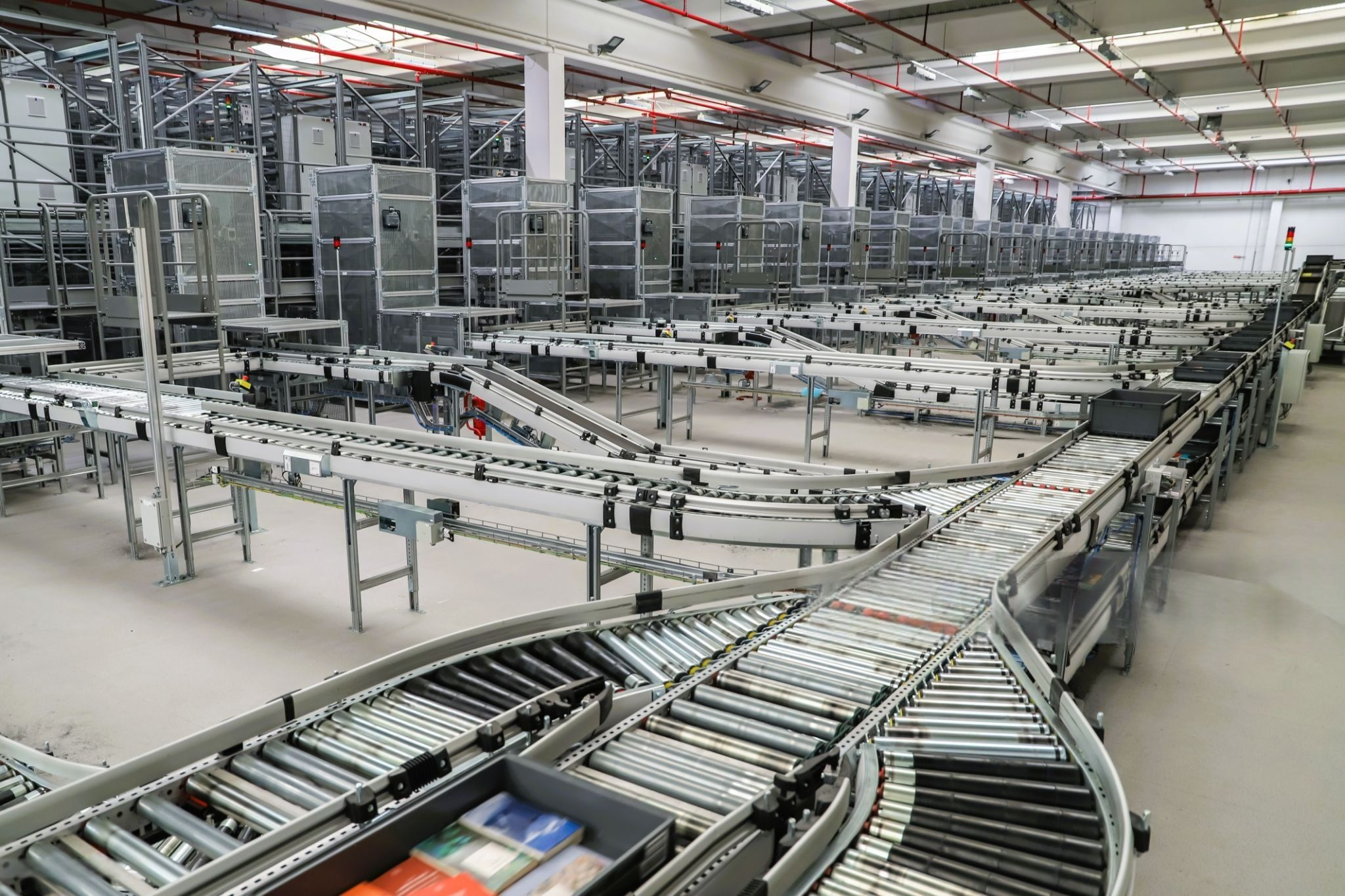
 IDEA Group design staff executing precision bore honing work
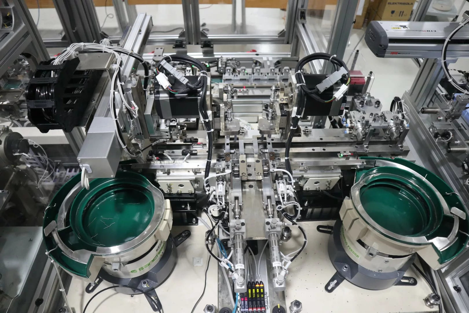
The task of extracting parts from a 2D or 3D assembly drawing into a new drawing sheet, fully dimensioned with tolerances, treatments, and symbols, results in a complete detailed drawing. This process is known as precision bore honing drawings. For short, it is called precision bore honing.
Thus, precision bore honing is a crucial step. It is considered the detailed design phase. The detailed drawings produced after precision bore honing are sent for machining. The quality, accuracy, and functionality of the part heavily depend on the precision of these detailed drawings, including:
- Incorrect dimensions will cause assembly failure.
- Improper tolerance values may also prevent proper assembly.
- Unreasonable surface roughness specifications can affect part performance and may cause defects or reduced quality in the final product.
- Other influencing factors.
II. Basic knowledge before precision bore honing
*Material of parts: The most commonly used materials include carbon steels, stainless steel (SUS), aluminum alloys (generally referred to as aluminum), and plastics such as POM, MC Nylon, PET, etc. There are also some other types of materials.
III. Precision bore honing instructions
3.1. Customer standards
Before starting any task for a given order, the first mandatory step is to thoroughly review the customer’s standards. Fully understand all requirements specified by the customer.
3.2. Drawing template
Precision bore honing requires a drawing template. If one is not yet available, request the project manager to provide the drawing template before starting work.
For 3D CAD software such as SolidWorks, Inventor, Catia, Creo, etc., changing the drawing template or scale updates automatically, making it easier as related properties adjust accordingly.
For 2D CAD software like AutoCAD, Icad, BricsCad, etc., changing the drawing or scale does not update automatically (unless pre-configured modules are installed). You must manually replace elements, and some properties won’t update automatically—this requires special attention. When changes occur, all properties must be adjusted to match the current drawing template.
3.3. Standard layer regulations
Each customer usually has specific layer standards that must be strictly followed when working on their drawings. Generally, for 3D CAD software, layers are preset and automatically adjusted during precision bore honing, provided you use the customer’s template. For 2D CAD software, you must manually adhere to the customer’s layer specifications.
Layer standards vary by order and customer. Basic layer types include:
- Outer contour layer: solid thick lines (outline), with thickness typically 0.25–0.3 mm.
- Hidden lines layer: dashed lines, thickness usually 0.18–0.2 mm.
- Centerline layer: dash-dot lines, thickness typically 0.13–0.15 mm.
- Dimension layer: same thickness as hidden lines. Annotation text is usually placed here too.
- Thin solid lines: used for thread roots, break lines, or partial section lines, with thickness matching centerlines.
- Double dash-dot lines: used for reference lines, thickness same as centerline.
- Other layer types as needed.
Note: In Icad software, line thickness is categorized into three levels: thick, medium, and thin. If the customer doesn’t specify, typically only medium and thin are used—medium for outer contours and thin for other lines.
3.4. Projection angles, view layout, and dimension origin
*Projection angle: Unlike the Vietnamese standard, projection angle according to JIS follows the third-angle projection system.

*View arrangement on drawings
Priority order is from ① to ⑤. Generally, in precision bore honing drawings and assembly drawings, views are arranged mainly from ① to ② (Primary view ①, top view, right side view). Besides this typical arrangement, there are other layout rules such as:
- According to directions used in the assembly drawing
- Based on machining rules

When arranging views on the drawing, select based on the specific case to ensure the final drawing is clear, easy to understand, and avoids confusion.
*Basic view layout rules for common part types
For cylindrical parts, arrange horizontally with the heavily machined side on the right (following machining rules).

Long, slender parts should also be arranged horizontally.

*Other part types.
Frames: Arrange according to actual working orientation. The bottom side corresponds to the ground level.

Brackets and bent plates

*Basic standards
- Standards for threaded holes, smooth holes, stepped holes, and tapered holes.
- Standards for other accessories.
The next part will provide a detailed step-by-step guide to the precision bore honing process. Stay tuned.